
WMAP Optics
The WMAP instrument consists of two back to back, symetric telescopes that produce two focal planes, A and B, on opposite sides of the spacecraft symmetry axis. A set of ten corrugated feeds lie in each focal plane and transport power to the amplification electronics.
Reflectors
The reflector design incorporates two back-to-back off-axis Gregorian telescopes with 1.4 m x 1.6 m primary reflectors and 0.9 m x 1.0 m secondary reflectors. The off-axis Gregorian optical design produces sufficient focal plane area, while satisfying the constraints of fitting the optical system in the Delta-rocket fairing envelope, placing the two focal planes in close proximity to one another, and minimizing sidelobe response with no obstructions in the beam. The principal focus is between the primary and the secondary. The reflector surfaces are shaped (i.e. designed with deliberate departures from conic sections) for optimal performance. Each primary is a (shaped) elliptical section of a paraboloid with a 1.4 m semi-minor axis and a 1.6 m semi-major axis. When viewed along the optic axis, the primary has a circular cross-section with a diameter of 1.4 m. The two focal planes produced by this arrangement are slightly convex with plate scales of ~15'/cm. The 99.5% encircled energy spot size diameter is less than 1 cm over a 15 x 15 cm region of the focal plane, and less than 0.33 cm over the central 8 x 8 cm region.
The reflector's optical surfaces are realized from a composite (XN70 carbon fiber facesheets with a KOREX honeycomb core) which in turn is vapor deposited with ~2.5 µm aluminum and 2.2 µm silicon oxide. The silicon oxide achieves the required thermal properties (A/E ~ 0.8, E ~ 0.5) while negligibly affecting the microwave signals. The reflectors are fixed-mounted onto a carbon-composite (XN-70 and M46-J) truss structure. The reflectors and their supporting truss structure were manufactured by Programmed Composites Inc. with the coating applied by Surface Optics Inc. Use of the composite materials minimizes both mass and on-orbit cool-down shrinkage. The reflectors are rigidly mounted to be in focus when cool so ambient preflight measurements are slightly out of focus. The microwave emissivity of the reflectors appears to be that of ideal shiny bulk aluminum.
In order to limit diffracted signals to less than 0.5 µK, diffraction shields are employed above, below, and to the sides of each secondary. In addition, the deployable solar panels and multi-layer insulation act as a Sun shield to guarantee that the secondaries remain at least 6 degrees into shadow during observing.
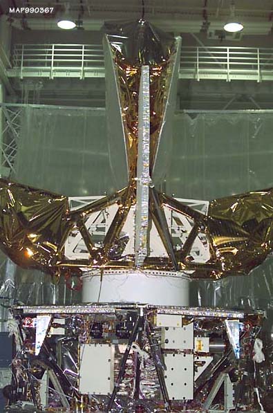
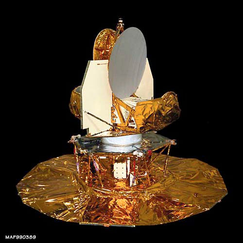
The left and middle photos below show side and end views of the WMAP optics as built. These photos also show the focal plane assembly (the white framed box) placed underneath the primary mirrors, and the large radiator panels designed to cool the sensitive HEMT amplifiers in the focal plane assembly. The right photo shows the full WMAP observatory after a solar panel/sun shield deployment test.

Feeds
The feed layouts and polarization directions for the 10 feeds in each focal plane are shown below. There is one pair of feeds at 22 GHz (K band), one pair at 30 GHz (Ka band), two pair each at 40 and 60 GHz (Q and V bands, respectively) and 4 pair at 90 GHz (W band). The larger number of channels at the higher frequencies is designed to provide roughly equal sensitivity at each frequency, since the higher frequency receivers are intrinsically noisier.
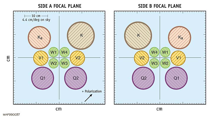
The feed design calls for as small an aperture as possible consistent with a primary edge taper requirement of -20 dB, and a length that places the throat of each differential feed pair in close proximity to the other. The feed aperture diameters scale inversely with frequency, while the primary is equally illuminated at each frequency, leading to a frequency dependent beam size. The smallest, highest frequency feeds are placed near the center of the focal plane where the spot size is smallest. The feeds are corrugated to produce beams with high symmetry, low loss, and minimal sidelobes: the extremely low loss HE_11 hybrid mode dominates. The phase center of each feed is kept as close as possible to its aperture, resulting in a frequency-independent beam for each feed. Since the distance from the focal plane to the spacecraft symmetry axis is nearly the same for all the feeds, the high frequency feeds are extended with low loss corrugated waveguide, while the low frequency feeds are "profiled" to reduce their length, while limiting excitation of the TE_11 mode to less than -30 dB.
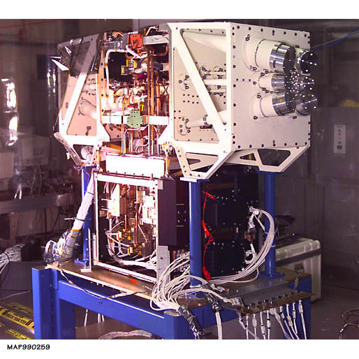
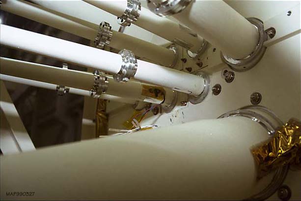
The left photo below shows the position of the feeds in the B-side focal plane (with temporary caps over the ends to prevent contamination). The right photo is a close-up of the feeds penetrating the focal plane bulkhead. Note that the feeds are manufactured in sections to facilitate machining.
Testing
The optical performance of the entire system has been both modeled and measured extensively. High resolution maps of the main beam lobe have been obtained at the Goddard ElectroMagnetic Anechoic Chamber while low resolution maps of the far sidelobes are obtained with an engineering model of the optics on the roof of Jadwin Hall at Princeton. The final determination of the main beam response was obtained in flight from observations of the bright planets, principally Jupiter. These data were used extensively in the processing of the flight data and detailed information about the beam response is an important component of the final WMAP data.